拖动LOGO至书签栏,立即收藏蜗牛文库

Designation: A395/A395M − 99 (Reapproved 2014)
Standard Specification for
Ferritic Ductile Iron Pressure-Retaining Castings for Use at Elevated Temperatures1
This standard is issued under the fixed designation A395/A395M; the number immediately following the designation indicates the year of original adoption or, in the case of revision, the year of last revision. A number in parentheses indicates the year of last reapproval. A superscript epsilon (s) indicates an editorial change since the last revision or reapproval.
This standard has been approved for use by agencies of the U.S. Department of Defense.
1.Scope
1.1This specification covers ductile iron castings for pressure-retaining parts for use at elevated temperatures. Cast ings of all grades are suitable for use up to 450°F. For temperatures above 450°F and up to 650°F, only Grade 60–40–18 castings are suitable (Note 1).
1.2Valves, flanges, pipe fittings, pumps, and other piping components are generally manufactured in advance and sup plied from stock by the manufacturer, jobber, or dealer.
1.3For supplemental casting requirements, Specification A834 may be utilized.
1.4The values stated in either SI units or inch-pound units are to be regarded separately as standard. The values stated in each system may not be exact equivalents; therefore, each system shall be used independently of the other. Combining values from the two systems may result in non-conformance with the standard.
NOTE 1—For service other than as specified in this section, reference should be made to Specification A536 for Ductile Iron Castings.2
2.Referenced Documents
2.1ASTM Standards:2
A247 Test Method for Evaluating the Microstructure of Graphite in Iron Castings
A370 Test Methods and Definitions for Mechanical Testing of Steel Products
A536 Specification for Ductile Iron Castings
A732/A732M Specification for Castings, Investment, Car bon and Low Alloy Steel for General Application, and Cobalt Alloy for High Strength at Elevated Temperatures
1 This specification is under the jurisdiction of ASTM Committee A04 on Iron Castings and is the direct responsibility of Subcommittee A04.02 on Malleable and Ductile Iron Castings.
Current edition approved April 1, 2014. Published April 2014. Originally approved in 1955. Last previous edition approved in 2009 as A395/A395M – 99 (2009). DOI: 10.1520/A0395_A0395M-99R14.
2 For referenced ASTM standards, visit the ASTM website, www.astm.org, or contact ASTM Customer Service at service@astm.org. For Annual Book of ASTM Standards volume information, refer to the standard’s Document Summary page on the ASTM website.
A834 Specification for Common Requirements for Iron Castings for General Industrial Use
E8 Test Methods for Tension Testing of Metallic Materials E10 Test Method for Brinell Hardness of Metallic Materials E186 Reference Radiographs for Heavy-Walled (2 to 41⁄2-in.
(50.8 to 114-mm)) Steel Castings
E280 Reference Radiographs for Heavy-Walled (41⁄2 to 12-in. (114 to 305-mm)) Steel Castings
E446 Reference Radiographs for Steel Castings Up to 2 in. (50.8 mm) in Thickness
E689 Reference Radiographs for Ductile Iron Castings E1806 Practice for Sampling Steel and Iron for Determina-
tion of Chemical Composition
F1476 Specification for Performance of Gasketed Mechani cal Couplings for Use in Piping Applications
F1548 Specification for Performance of Fittings for Use with Gasketed Mechanical Couplings Used in Piping Applica tions
2.2Manufacturer’s Standardization Society of the Valve and Fittings Industry Standard:3
SP 25 Standard Marking Systems for Valves, Flanges, Pipe Fittings, and Unions
3.Classification
3.1Castings ordered to this specification are classified by grades based on mechanical property requirements, as listed in Table 1. See note following Table 1.
4.Ordering Information
4.1Orders for material under this specification shall include the following applicable information:
4.1.1Drawing, catalog number, or part identifications,
4.1.1.1For grade 65-45-15, drawing indicating critical ar ea(s) of casting (see 7.2.2 and 7.3.2).
4.1.2Quantity (weight or number of pieces),
4.1.3ASTM designation and year of issue,
4.1.4Grade (See Table 1), if a Grade is not specified, the manufacturer shall supply grade 60-40-18.
3 Available from Manufacturers Standardization Society of the Valve and Fittings Industry (MSS), 127 Park St., NE, Vienna, VA 22180-4602, http://www.mss-hq.org.
Copyright © ASTM International, 100 Barr Harbor Drive, PO Box C700, West Conshohocken, PA 19428-2959. United States
TABLE 1 Mechanical Property Requirements
7.1.1 The ductile iron as represented by the test specimens shall conform to the mechanical property requirements in Table 1.
4.1.5Heat-treating requirements (see 5.2.1),
4.1.6Pressure test requirements (see 7.4.3),
4.1.7Test samples from castings (see 11.1.1 and 12.1.1),
4.1.8Test coupons size (see 11.2),
4.1.9Metallographic option (see 12.1.1),
4.1.10Place of inspection (see 16.1),
4.1.11Certification requirements (see 17.1),
4.1.12Identification marking (see 18.2), and
4.1.13Supplemental Requirements (see 1.4, 7.4.2, S1 and S2).
5.Materials and Manufacture
5.1The melting method and the nodularizing practice shall be optional with the foundry.
5.2Except as provided in 5.2.1, all castings Grade 60-40-18 shall be given a ferritizing heat treatment that produces essentially a ferritic structure that contains no massive car bides.
5.2.1When specified in the purchase order, Grade 60-40-18 castings may be provided in an as-cast condition provided they comply with the requirements of 7.1 and 7.2.1.
5.2.2Castings supplied in accordance with 5.2.1 may be stress relieved by agreement between the manufacturer and purchaser.
5.3Castings Grade 65-45-15 may be provided in as-cast condition or heat treated, provided they comply with the requirements of 7.1, 7.2.2, and 7.3.2.
6.Chemical Requirements
6.1The casting shall conform to the following requirements for chemical composition (Note 2):
Total carbon, min, % 3.00
Silicon, max, % 2.50
Phosphorus, max, % 0.08
6.1.1The chemical analysis for total carbon shall be made on chilled cast pencil type specimens or from thin wafers approximately 1⁄32 in. [0.8 mm] thick cut from test coupons. Drillings are not reliable because of the probable loss of graphite.
6.1.2For each reduction of 0.01 % below the maximum specified phosphorus content, an increase of 0.08 % silicon above the specified maximum will be permitted up to a maximum of 2.75 %.
NOTE 2—Silicon contents above 2.75 %, or phosphorus contents above
0.08 % have a tendency to lower the impact resistance of the material. If the carbon content is below 3.00 %, excess cementite may form during cooling and if this is not removed during heat treatment, the impact resistance of the material may be lowered.
7.Requirements
7.1Tensile Properties:
7.2
Hardness:
7.2.1For Grade 60–40–18, the hardness of the castings and test specimens shall be within the limits in Table 1.
7.2.2For Grade 65–45–15, the hardness of test specimen and the critical area(s) of the casting, as identified on the casting drawing, shall be within the limits in Table 1. If the grade 65–45–15 casting drawing does not have critical area(s) of the casting identified, all areas of the casting shall be within the hardness limits in Table 1.
7.3Microstructure:
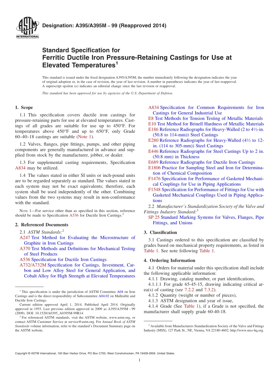
7.3.1For Grade 60-40-18, the microstructure of the sepa rately cast test coupon or the casting shall be essentially ferritic and contain no massive carbides, and have a minimum of 90 % Type I and Type II Graphite as in Fig. 1 or Plate I of Test Method A247.
7.3.2For Grade 65-45-15, the microstructure of the critical areas of the casting, as identified on the casting drawing, shall be 45 % pearlitic, maximum, contain no massive carbides, and have a minimum 90 % Type I and Type II Graphite as in Fig. 1 or Plate I of Test Method A247.
7.4Pressure Test Requirements :
7.4.1Each pressure retaining Grade 60-40-18 casting shall be tested after machining to the test pressure specified by the applicable standard of ANSI, ASME Boiler and Pressure Vessel Code, or other pertinent code, and shall show no leaks.
7.4.2Castings Grade 65-45-15 manufactured under this specification shall be capable of passing hydrostatic test(s) compatible with the rating of the finished cast component. Such tests shall be conducted by the casting manufacturer only when Supplementary Requirement S2 is specified.
7.4.3Castings Grade 60-40-18, ordered under this specifi cation not covered by ANSI standards and ASME Pressure Vessel Code, and castings for special service applications, shall be tested to such pressures as may be agreed upon by the manufacturer and the purchaser.
7.4.4For castings Grade 60-40-18, it is realized that the foundry may be unable to perform the hydrostatic test prior to shipment, or that the purchaser may wish to defer testing until additional work or machining has been performed on the casting. Castings ordered in the rough state for final machining by the purchaser may be tested hydrostatically prior to ship ment by the manufacturer at pressures to be agreed upon with the purchaser. However, the foundry is responsible for the satisfactory performance of the castings under the final hydro static test.
8.Workmanship and Finish
8.1The surface of the casting shall be examined visually and shall be free from adhering sand, scale, cracks, and hot tears. Any other surface discontinuities shall meet visual acceptance standards specified in the order.
NOTE 1—Graphite types are identical with Plate 1 of Test Method A247 and are so identified.
FIG. 1 Suggested Classification of Graphite Form in Ductile Cast Iron
9.Repair
9.1Castings for valves, flanges, pipe fittings, pumps, and other piping components ordered under applicable ANSI stan dards shall not be repaired by plugging, welding, brazing, or impregnation.
9.2Castings Grade 60-40-18 not covered in 9.1 which leak on hydrostatic tests may be repaired by plugging, provided the following requirements are met:
9.2.1No welding or brazing is permitted.
9.2.2The diameter of the plug shall not exceed the diameter of a standard 2 in. [ISO R2] pipe plug.
9.2.3The plugs, where practical, shall conform in all dimensions to the standard ISO 3⁄8 plugs. In addition, they shall have full thread engagement corresponding to the thick ness in the repaired section. Where a tapered plug is imprac tical because of the excess wall thickness in terms of plug diameter and coincident thread engagement, other types of plugs may be used provided both full engagement and effective sealing against pressure are obtained. Where possible, the ends
of the plug should be ground smooth after installation to conform to the inside and outside contours of the wall of the pressure vessel or pressure part.
9.2.4The material from which the plug is manufactured shall conform in all respects to the materials specifications that apply to the pressure vessel or pressure part.
9.2.5The area adjacent to the drilled hole shall be examined by radiography, and shall meet the Level 3 acceptance require ments of Reference Radiographs E689 and supporting Refer ence Radiographs E446, E186, or E280 as applicable and defined in accordance with Reference Radiographs E689.
9.2.6The thickness of any repaired section in relation to the size of the plug used shall not be less than that given in Table 2.
9.2.7The minimum radius of repaired sections of cylinders or cones in relation to the size of plug used shall not be less than that given in Table 3.
9.2.8A repaired area may consist of a maximum of three plugs with a spacing such that the ligaments between adjacent
TABLE 2 Minimum Thickness of Repaired Sections
Iron Pipe Size Plug, in. Minimum Thickness Repaired Section, in. [mm]
1⁄8 11⁄32 [8]
1⁄4 7⁄16 [10]
3⁄8 1⁄2 [13]
1⁄2 21⁄32 [17]
3⁄4 3⁄4 [19]
1 13⁄16 [21]
11⁄4 7⁄8 [23]
11⁄2 15⁄16 [24]
2 1 [26]
TABLE 3 Minimum Radius of Repaired Sections
Iron Pipe Size Plug, in. Minimum Radius of Cylinder or Cone, in. [mm]
1⁄8 9⁄16 [15]
1⁄4 11⁄16 [18]
3⁄8 11⁄16 [28]
1⁄2 11⁄4 [32]
3⁄4 2 [52]
1 21⁄2 [64]
11⁄4 4 [104]
11⁄2 51⁄4 [136]
2 81⁄8 [208]
plugs shall not be less than listed in Table 4. Other defective areas may also be repaired by plugging provided the minimum ligament between plugs in adjacent areas is not less than twice the distance from the nearest plug, the values for which are listed in Table 4.
9.3Surface imperfections in castings Grade 60-40-18 other than valves, flanges, pipe fittings, pumps, and other piping components may be repaired by plugging provided the depth of the plug is not greater than 20 % of the thickness of the casting section and the diameter of the plug is not greater than its length. Repair of surface defects may not be done on pressure-containing portions of castings. The plug need not be threaded. The conditions of 9.2.1 and 9.2.4 shall also be satisfied.
10.Sampling
10.1A lot shall consist of one of the following:
10.1.1All the metal from a single heating in a batch-type melting furnace.
10.1.2All the metal poured from two or more batch-type melting furnaces into a single ladle or a single casting.
TABLE 4 Minimum Ligament Between PlugsA,B
10.1.3
All the metal poured from a continuous melting furnace for a given period of time between changes in charge, processing conditions, or aim-for chemistry, or 8 h, whichever is the shorter period.
11.Test Coupon
11.1The separately cast test coupons poured from the same lot as the castings they represent from which the tension test specimen is machined shall be cast to the size and shape shown in Fig. 2, Fig. 3, or Fig. 4. Cast coupons shall be identified with the castings they represent. Sectioning procedure for removing test specimens from Y-blocks is shown in Fig. 5.
11.1.1Test samples may be removed from castings at locations designated on a drawing or as agreed to by manu facturer and purchaser.
11.1.2Test bars removed from castings shall conform to Fig. 6. The testing diameter shall be 1⁄2 in. [12.5 mm] if possible. Smaller diameters shall be utilized if necessary.
11.2The test coupon size shall be as mutually agreed upon between the manufacturer and purchaser. In the absence of agreement, it shall be the option of the manufacturer.
11.3The test coupons shall be cast in molds made of suitable core sand having a minimum wall thickness of 11⁄2 in. [38 mm] for the 1⁄2 in. [12.5 mm], 1 in. [25 mm] sizes, and 3 in. [75 mm] for the 3 in. [75 mm] size. The coupons shall be left in the mold until they have changed to a black color (approximately 900°F [480°C] or less). The keel block as shown in Fig. 2 or the modified keel block produced from the mold shown in Fig. 4 may be substituted for the 1 in. [25 mm] block shown in Fig. 3.
11.4When investment castings are made to this specification, the manufacturer may use test specimens cast to size incorporated in the mold with the castings or separately cast to size using the same type of mold and the same thermal conditions that are used to produce the castings. These test
Nominal Plug
Minimum Ligament Between Plugs, in. [mm]
Diameter, in. 1⁄8, 1⁄4, 3⁄8 1⁄2, 1⁄4 1, 11⁄4 11⁄2, 2
1⁄8, 1⁄4, 3⁄8 25⁄8 [67] 41⁄8 [105] 65⁄8 [169] 91⁄2 [242]
1⁄2, 3⁄4 41⁄8 [105] 41⁄8 [105] 65⁄8 [169] 91⁄2 [242]
1, 11⁄4 65⁄8 [169] 65⁄8 [169] 65⁄8 [169] 91⁄2 [242]
11⁄2, 2 91⁄2 [242] 91⁄2 [242] 91⁄2 [242] 91⁄2 [242]
A Based on efficiency of 80 %.
B Example: Assume three plugs are required for repair, one 1⁄8 in., one 3⁄8 in., and one 11⁄2 in. The minimum distance permitted is as follows:
Ligament distance between 1⁄8 and 3⁄8-in. plugs is 25⁄8 in. [67mm].
Ligament distance between 1⁄8 and 11⁄2-in. plugs is 91⁄2 in. [242 mm].
Ligament distance between 3⁄8 and 11⁄2-in. plugs is 91⁄2 in. [242 mm]. NOTE 1—The length of the keel block shall be 6 in. [152 mm]
FIG. 2 Keel Block for Test Coupons
“Y” Block Size
Dimensions For Castings of Thickness Less Than 1⁄2 in.
[13 mm] For Castings of Thickness 1⁄2 in. [13 mm] to
11⁄2 in. [38 mm] For Castings of Thickness of 11⁄2 in. [38 mm] and Over
in. [mm] in. [mm] in. [mm]
A 1⁄2 [13] 1 [25] 3 [75]
B 15⁄8 [40] 21⁄8 [55] 5 [125]
C 2 [50] 3 [75] 4 [100]
D 4 [100] 6 [150] 8 [200]
E 7 [175] approx 7 [175] approx 7 [175] approx
FIG. 3 Y-Blocks for Test Coupons
specimens shall be made to the dimensions shown in Fig. 1 of Specification A732/A732M or Fig. 5 and Fig. 6 of Test Methods and Definitions A370.
11.5The manufacturer shall cast a sufficient number of test coupons to provide for each ferritizing anneal. The test coupons shall be heat treated with the castings they represent. Sectioning of the test coupons prior to heat treating is not permitted.
11.6The metallographic examination shall be made on a test lug from the test coupon shown in Fig. 7 or from a casting; or from a representative test coupon poured with the casting(s). The test coupon shall represent the metal treated with the nodularizing agent.
12.Number of Tests and Retests
12.1One tension test shall be made from sections cut from the test coupons (Fig. 5) required by Section 11.
12.1.1Unless otherwise stated in the contract or order for castings, a metallographic examination may be substituted for the tension test when separately cast test coupons are used. When the microstructure option is used, a minimum of one tension test is required from each day’s melt and for each heat treatment (see 12.2).
12.2If any tension test specimen shows obvious defects, another from the same coupon, or from another coupon/or representing the same metal and the same anneal charge, may be tested. If an apparently sound test specimen fails to conform to this specification, castings may be re-annealed, if required, and two retests made. If either retest fails to conform to this specification, the castings they represent shall be rejected.
13.Tension Test Specimen Preparation
13.1The standard machined 1⁄2 in. [12.5 mm] round tension test specimen with 2 in. [50 mm] gauge length as shown in Fig.
6 shall be used except where the 1⁄2 in. [12.5 mm] Y-block test coupon is required. In this case, either of the small size specimens, 0.375 or 0.250 in. [9 or 6.5 mm] round as shown in Fig. 6, shall be used.
14.Test Methods
14.1Chemical analysis shall be made in accordance with Test Method E1806.
14.2The yield strength shall be determined in accordance with Test Methods E8 using one of the following methods:
14.2.1The 0.2 % off-set method, or
14.2.2Extension under load method where the yield strength may be determined as the stress producing an elonga tion under load of 0.375 %; that is, 0.0075 in. [0.19 mm] in a gauge length of 2 in. [50 mm].
14.3The hardness of the ductile iron as represented by the test specimens and castings shall be determined in accordance with Test Method E10.
14.4The percentage of each graphite type shall be deter mined by manual counting, semi-automatic, or automatic image analysis methods. The sum of all graphite types shall total to 100 %.
15.Records
15.1Records of the chemical composition, mechanical properties, and metallographic examination, when applicable, shall be systematically made and maintained.
16.Inspection
16.1Unless otherwise specified in the contract or purchase order, the manufacturer shall be responsible for carrying out all the tests and inspection required by this specification.
16.2The inspector representing the purchaser shall have entry at all time, while work on the contract of the purchaser is being performed, to all parts of the manufacturer’s works which concern the manufacturer of the material ordered. The manufacturer shall afford the inspector all reasonable facilities to satisfy him that the material is being furnished in accordance with these specifications. Unless otherwise specified, all tests and inspection shall be made at the place of manufacture or by an approved independent laboratory prior to shipment, and shall be so conducted as not to interfere unnecessarily with the operation of the works.
17.Certification
17.1When agreed upon in writing by the purchaser and the supplier, a certification shall be made on the basis of accep tance of the material. This shall consist of a copy of the manufacturer’s test report or a statement by the supplier accompanied by a copy of the test results, that the material has been sampled, tested, and inspected in accordance with the provisions of this specification. Each certification so furnished shall be signed by an authorized agent of the supplier or manufacturer.
18.Product Marking
18.1Castings for valves, flanges, pipe fittings, and unions shall be marked for material identification in accordance with
FIG. 4 Mold for Modified Keel Block
the Standard Marking System for Valves, Flanges, Pipe Fittings, and Unions, SP-25. Castings for gasketed mechanical couplings and fittings may be marked in accordance with Specification F1476 or F1548 respectively.
18.2Castings, other than valves, flanges, pipe fittings, and unions, shall be identified subject to agreement by the manu facturer and the purchaser.
18.3
Marking shall be in such a position as not to injure the usefulness of the castings.
19.Keywords
19.1casting; ductile iron; mechanical properties; pressure-retaining; pressure test; tensile strength; tension testing; yield strength
FIG. 5 Sectioning Procedure for Y-Blocks
NOTE 1—The reduced section may have a gradual taper from the ends toward the center, with the ends not more than 0.005 in. [0.13 mm] larger in diameter than the center on the standard specimen, and not more than 0.003 in. [0.076 mm] larger in diameter than the center on the small size specimens.
NOTE 2—If desired, on the small size specimens, the length of the reduced section may be increased to accommodate an extensometer. However, reference marks for measurement of elongation should nevertheless be spaced at the indicated gauge length.
NOTE 3—The gauge length and fillets shall be as shown, but the ends may be of any form to fit the holders of the testing machine in such a way that the load shall be axial. If the ends are to be held in grips, it is desirable to make the length of the grip section great enough to allow the specimen to extend into the grips a distance equal to two thirds or more of the length of the grips.
Standard Specimen, in. [mm] Small Size Specimens Proportionate to Standard, in. [mm]
Dimensions
FIG. 6 Standard 1⁄2-in. [12.5–mm] Round Tension Test Specimen with 2-in. [50.0–mm] Gauge Length and Examples of Small Size Speci mens Proportional to the Standard Specimen
FIG. 7 Test Coupon for Microscopical Examination of Ductile Iron
SUPPLEMENTARY REQUIREMENTS
The following supplementary requirement shall not apply unless specified in the purchase order.
S1. For Castings Grade 60-40-18, a microstructure test lug is to be cast attached to the casting at the location designated on the casting drawing. The microstructure of the test lug shall be essentially ferritic and contain no massive carbides.
S2. Pressure Test, Casting Grade 65-45-15.
S2.1 A hydrostatic test at a pressure agreed upon by the manufacturer and the purchaser shall be applied by the manufacturer.
ASTM International takes no position respecting the validity of any patent rights asserted in connection with any item mentioned in this standard. Users of this standard are expressly advised that determination of the validity of any such patent rights, and the risk of infringement of such rights, are entirely their own responsibility.
This standard is subject to revision at any time by the responsible technical committee and must be reviewed every five years and if not revised, either reapproved or withdrawn. Your comments are invited either for revision of this standard or for additional standards and should be addressed to ASTM International Headquarters. Your comments will receive careful consideration at a meeting of the responsible technical committee, which you may attend. If you feel that your comments have not received a fair hearing you should make your views known to the ASTM Committee on Standards, at the address shown below.
This standard is copyrighted by ASTM International, 100 Barr Harbor Drive, PO Box C700, West Conshohocken, PA 19428-2959, United States. Individual reprints (single or multiple copies) of this standard may be obtained by contacting ASTM at the above address or at 610-832-9585 (phone), 610-832-9555 (fax), or service@astm.org (e-mail); or through the ASTM website (www.astm.org). Permission rights to photocopy the standard may also be secured from the ASTM website (www.astm.org/ COPYRIGHT/).
1、当您付费下载文档后,您只拥有了使用权限,并不意味着购买了版权,文档只能用于自身使用,不得用于其他商业用途(如 [转卖]进行直接盈利或[编辑后售卖]进行间接盈利)。
2、本站所有内容均由合作方或网友上传,本站不对文档的完整性、权威性及其观点立场正确性做任何保证或承诺!文档内容仅供研究参考,付费前请自行鉴别。
3、如文档内容存在违规,或者侵犯商业秘密、侵犯著作权等,请点击“违规举报”。
碎片内容